Saturday 31 October 2015

Mechanical Pump


        Mechanical Pump: The mechanically operated diaphragm type fuel pump is operated by an eccentric mounted on the camshaft of the engine. The pump consists of a spring loaded flexible diaphragm actuated by a rocker arm. The rocker arm is actuated by the eccentric. Spring loaded valves are there in the inlet and outlet of the pump. These valves ensure flow of fuel in the proper direction.
        As the rocker arm is moved by the eccentric, the diaphragm is pulled down against the spring force. This movement causes a partial vacuum in the pump chamber. Now the delivery valve remains closed and the suction valve opens. This admits fuel into the pump chamber. At the maximum position of the eccentric, the diaphragm is flexed to the maximum extent after this further rotation of the eccentric will release the rocker arm. Now the rocker arm will simply follow eccentric by the action of the return spring. The
diaphragm spring will now push the diaphragm upwards and the force the fuel to flow out, opening the delivery valve, into the delivery tube. Now the suction valve remains closed.
         In this pump, the downward movement is caused by the rocker arm, while the delivery stroke is achieved by the force of the diaphragm spring  The diaphragm spring is so designed that the fuel pressure is suitable balanced by the buoyancy of the float system of the carburetor. As such, when deliver fuel to the carburetor. In this case, the rocker arm simply continues to rock while the diaphragm remains at or near its lowest travel. However, as the carburetor uses fuel, the needle valve opens to admit fuelinto the float bowl. Now the diaphragm moves downward by the rocker action and sucks the fuel to deliver back the same when required. This self regulating feature helps the pump to deliver the correct quantity of fuel at all operating conditions.


Friday 16 October 2015

PETROL ENGINE FUEL SYSTEM


Introduction: The fuel system of an Internal Combustion engine is intended to produce a combustibl  mixture composed of the fuel stored in the fuel tank and the atmospheric air, and then deliver both to the cylinders. Petrol engines use light grade gasoline.


Components of fuel feed system: 

The fuel feed system of a petrol engine are having the following components.

1. Fuel Tank
2. Fuel Pump
3. Fuel Filter
4. Carburetor
5. Intake manifold
6. Fuel lines
7. Fuel Gauge

Oil Bath Type Air Cleaner


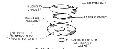
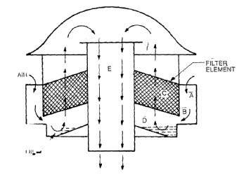
Dry Type Air Cleaner


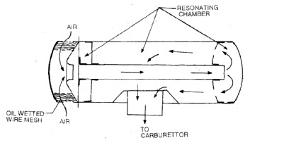
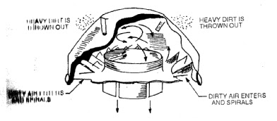
Centrifugal Type air cleaner


OIL BATH TYPE AIR CLEANER


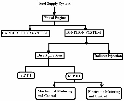
Types of Fuel Feed Systems: The fuel from the fuel tank can be supplied to the engine cylinder by the following systems.

1. Gravity System. 
2. Pressure system 
3. Vacuum System
4. Pump System 
5. Fuel Injection System.

Functions of fuel feed system:

1. To store the fuel in the fuel tank.
2. To supply fuel to the engine to the required amount and in proper conditions.
3. To indicate o the driver the fuel level in the fuel tank.

          In the gravity fuel feed system, the fuel tank is mounted at a place higher than that of the carburetor. The fuel flows from the tank to the carburetor due to the gravitational force. Thus the system does not require any fuel pump. The fuel tank is directly connected to the carburetor. Scooters and motorcycles use this system.
          In pressure system, a pressure sealed tank is used. The pressure is created in the tank by means of a separate pump. For starting, the pump is primed by cam which produces pressure in the tank and fuel flows to the carburetor. In this system the tank can be placed above or below the carburetor.
          In vacuum system, the engine suction is used for sucking the fuel from the main tank to the auxiliary fuel tank from where it flows by gravity to the carburetor.
          In pump system, a fuel pump is used to feed the fuel from the fuel tank to the carburetor. The pump is driven either by the cam shaft or electrically. In this system, the fuel tank can be placed at any suitable position in the vehicle.
          In the fuel injection system, a fuel injection pump is used in place of carburetor. The fuel is atomized by means of a nozzle and then delivered into an air stream. Separate fuel injection system is used for each cylinder which controls the mixture under different load and speed conditions.

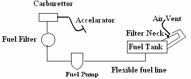
Fuel Tank: The fuel tank is made of sheet metal. It is usually attached to the frame at a rear of vehicle. Its capacity ranges from 70 to 120 liters. The filler neck of the tank is closed by a cap. In some other tanks, there is a filtering element at the fuel line connection to convert dirt and prevent it from reaching to the pump and carburetor. A drain plug is provided at the bottom for emptying the tank. The tank also contains the float unit of the fuel gauge. It may also have a vent pipe which allows air to escape when the tank is being filled. In the cars, that are equipped with vapor recovering system, thevent pipe is connected to condenser which contains the vaporized gasoline in the tank and prevents its escape into the air.

Fuel line: The copper or steel tubes and hoses are used for connecting fuel tank with pump with carburetor. The tube connecting the fuel tank and pump is fastened rigidly to the frame or body. The first and last portion
generally consists of a flexible tube that joints the rigid line to the fuel tank or to the pump. This allows the fuel tank to oscillate with the body and the pump with the engine without breaking or loosening the line.

Fuel Filters: The fuel is filtered at different stages in a fuel supply system. Therefore, many fuel filters are used in the fuel circuit. The fuel filter serves the purpose of filtration in the fuel delivery system by preventing foreign particles from entering into the fuel pump and the carburetor. The modern filtration practice employs a combination of coarse and fine filters.
         Course filters are incorporated within the fuel tank.

         Medium coarse filter are outside the fuel tank and on the inlet side of the pump.
         Fine filters of built in surface type at inlet of fuel pumps pumping chamber.
         Fine filter in pipe line is between fuel pump and the carburetor.


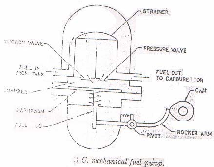
Fuel pumps: A fuel pump is used to deliver fuel from the fuel tank to the float chamber of carburetor. Main types of fuel pumps commonly used on auto vehicles.

1. A.C. Mechanical pump
2. S.U. Electrical pump
3. Electromagnet pump
4. Combined pump (fuel pump with a vacuum
pump)


Tuesday 13 October 2015

Side valve and over head valve Operating Mechanisms


The valves used in four stroke engines are operated by two mechanisms.

1. valve mechanism for operating the valve in engine block or straight or side
valve mechanism.

2. Valve mechanism for operating the valve in cylinder head or over head
valve mechanism.

Side valve operating mechanism


     This mechanism is used in the engine block. It is mostly adopted in L,T and F type engine heads. The valve stem slides up and down in the valve stem guide which acts as a slipper bearing. It also prevents the gases from passing from the valve port to the valve chamber of the engine block. Valve spring is fitted between the engine block and spring retainer, which keeps the valve closed tightly on the valve seat, until lifted by the valve tappet by the rotation of the cam. The tappet or lifter is held between guide which is generally a part of the engine block. Adjusting screw is provided on the tappet to adjust the clearance between the upper end of the tappet and the bottom of the valve stem. As the cam rotates, it lifts the tappet which lifts the valve to the open position thus connecting the valve part tot the combustion chamber.
     Valve seat inserts are fitted on the valve seats. These inserts are in the form of rings tapered grounded to suit the valve faces, and made of special alloy steels. Usually they are used only on exhaust valve seats. They reduce wear and can be replaced when worn out.


Over head valve mechanism:


     It is used in I type and F type engine heads. This type valve operating mechanism requires a push rod and a rocker arm. As the cam rotates, it lifts the valve tappet or the lifter which actuates the push rod. The push rod rotates the rocker arm about a shaft- the rocker arm shaft, or a ball joint in some designs to cause one end to push down on the valve stem to open the valve, thus connecting the valve port with the combustion chamber. In this mechanism, the valve tappet clearance is between the rocker arm and valve stem. It is adjusted by means of an adjusting screw on the rocker-arm end that contacts the push rod.


Sunday 11 October 2015

Four Stroke Engine:


              The four stroke engine comprises of suction, compression, power or working and exhaust strokes.

1. Suction Stroke: When the piston moves from TDC to BDC the inlet valve opens and due to the downward movement of piston a partial vacuum is created in the cylinder above the piston. Due to this partial vacuum air is sucked in at the end of stroke the inlet valve closes.

2. Compression Stroke: When the piston starts moving from BDC to TDC the air which has been trapped in the cylinder starts getting compressed, when the piston reaches near TDC, the trapped air gets so compressed that its temperature reaches between 5000C to 6500C. this higher increase in temperature is because of higher compression ratio, in this stroke both valves remain closed.

3. Power Stroke: At the end of compression stroke diesel oil is sprayed in fine atomized form to the burning hot air which has attained temperature of approximately 5000 to 6500C here we would like to mention that self ignition temperature of diesel fuel at atmospheric pressure is 3500C to 4500C as such atomized fuel in hot air gets ignited in more or less rapid explosion making gases to expand. We have earlier studied that piston is the only moving part in the cylinder.

4. Exhaust Stroke: In this stroke, the exhaust valve opens and due to moving of piston from BDC to TDC, the burnt gases are pushed out. The inlet valve opens in suction stroke but as a matter of fact it opens 100 to
220 before TDC in exhaust stroke. So that valve is fully open when piston starts moving down and enough time is given for air to get it. The inlet valve remains open in compression stroke 200 to 300 after BDC. This
once again is to allow air which was coming to cylinder to cylinder with great velocity to fill cylinder completely.


Cylinder arrangement of Petrol engines


The classification of petrol engines on the arrangement of cylinder is as follows.

1. Inline arrangement – 2 in line, 3 inline, 4 inline, 6 inline and 8 inline.
2. V arrangement – v-4, v-6, v-8 and v-12.
3. Opposed cylinder or flat arrangement – flat 2, flat 4 and flat 6.
4. Radial cylinder arrangement.


Construction and working of 2 Stroke and 4 stroke engines Two Stroke engine:


                   The two stroke engine there are two strokes namely upward stroke and downward stroke. In a two stroke engine, the two strokes are completed in two strokes of the piston or one complete revolution of the crankshaft. Upward stroke: during the upward stroke the piston moves upward from bottom dead centre to top dead centre. The air fuel mixture or air is compressed in the combustion chamber of the cylinder. Due to upward movement of the piston, a partial vacuum is created in the crankcase, and a new charge is drawn into the crankcase through the uncovered inlet port. The exhaust port and transfer port are covered when the piston is at top dead centre position. The compressed charge is ignited in the combustion chamber.

                    Downward stroke: As soon as the charge is ignited, the hot gases compress the piston which moves downward, rotating the crankshaft thus doing the useful work. During this stroke the inlet port is covered by the piston and the new charge is compressed in the crankcase. Further downward movement
of the piston uncovers first the exhaust port and then the transfer port, and hence the exhaust starts through the exhaust port. As soon as the transfer port opens, the charge through it is forced into the cylinder. The charge strikes the deflector on the piston crown, rises to the top of the cylinder and pushes out most of the exhaust gases. The piston is now at bottom dead centre position. The cylinder is completely filled with the fresh charge, although it is then repeated, the piston making two strokes for each revolution of the crankshaft.


Saturday 10 October 2015

Petrol Engines


Materials used, function and Constructional details of Petrol Engine
Components


Engine consists of the following parts.

1. Cylinder block 
2. Cylinder head
3. Crankcase 
4. Piston
5. Piston Rings 
6. Piston Pin
7. Connecting Rod 
8. Crankshaft
9. Flywheel 
10. Valves and valve mechanism
11. Rocker Arm 
12. Camshaft

besides the above components engine contain so many accessories like aircleaner, oil filter, automatic chokes, automatic heat controls, spark plug, ignition devices, carburetors, manifolds, vibration damper etc.
Materials used for various components: The cylinder block and cylinder heat are made of gray cast iron and
sometimes with addition of nickel and chromium. Some cylinder blocks are cast from aluminum, cast iron or steel. The cylinder blocks are made of casting process. Small engine cylinder blocks walls are plated with chromium to reduce wall wear and to increase their service life. The cylinder gaskets are made of copper-asbestos, steel asbestos and stainless steel.

The upper part of the crankcase is made of ferrous alloy or semi-steel to provide a stronger and harder casing.

The cylinder liners are barrels made of special alloy iron containing silicon, manganese, nickel and chromium. The cylinder liners are centrifugal castings. The piston is the most important part in the engine which converts chemical energy into mechanical power. As the piston is to convey the expansion of the gases via connecting rod it is made of aluminum alloy by the process of either cast or forged. As the conductivity of aluminum alloy is more than cast iron, it is made of aluminum alloy. The piston rings are coated to minimize the wear. The piston rings are coated with chromium plating to decrease the rate of wear. Ring coating absorbs oil
thus improving lubrication. The piston rings are castings.

The connecting rod is generally I-beam cross-section and is made of forged steel. Aluminum alloy is also used for connecting rods. But they are carefully matched in sets of uniform weight in order to maintain engine balance. The connecting rod is made of forging process. The crankshaft is made of casting or forging of heat treatment alloy steel and is machined and ground to provide suitable journals for the connecting rod and main bearings. The flywheel is a fairly heavy bulk mass of steel attached to the crankshaft. The size of the flywheel depends upon the number of cylinders and the general construction of the engines. During the power stroke the engine tends to speed up and during the other three strokes it tends to slow down. The inertial of the flywheel tends to keep it running at constant speed. The valves are usually made of austenitic stainless steel which is a corrosion

and heat resistant material. Exhaust valve is made of silchrome steel which is an alloy of silicon and chromium with unusual resistance to heat. Inlet valve is usually made of nickel chromium alloy steel.


Friday 9 October 2015

Petrol Engines


Materials used, function and Constructional details of Petrol Engine Components

Engine consists of the following parts.

1. Cylinder block 2. Cylinder head
3. Crankcase 4. Piston
5. Piston Rings 6. Piston Pin
7. Connecting Rod 8. Crankshaft
9. Flywheel 10. Valves and valve mechanism
11. Rocker Arm 12. Camshaft

besides the above components engine contain so many accessories like aircleaner, oil filter, automatic chokes, automatic heat controls, spark plug, ignition devices, carburetors, manifolds, vibration damper etc.
Materials used for various components:

The cylinder block and cylinder heat are made of gray cast iron and sometimes with addition of nickel and chromium. Some cylinder blocks are cast from aluminum, cast iron or steel. The cylinder blocks are made of
casting process. Small engine cylinder blocks walls are plated with chromium to reduce wall wear and to increase their service life.

The cylinder gaskets are made of copper-asbestos, steel asbestos and stainless steel. The upper part of the crankcase is made of ferrous alloy or semi-steel to provide a stronger and harder casing.
The cylinder liners are barrels made of special alloy iron containing silicon, manganese, nickel and chromium. The cylinder liners are centrifugal castings.

The piston is the most important part in the engine which converts chemical energy into mechanical power. As the piston is to convey the expansion of the gases via connecting rod it is made of aluminum alloy by the process of either cast or forged. As the conductivity of aluminum alloy is more than cast
iron, it is made of aluminum alloy.

The piston rings are coated to minimize the wear. The piston rings are coated with chromium plating to decrease the rate of wear. Ring coating absorbs oil thus improving lubrication. The piston rings are castings.
The connecting rod is generally I-beam cross-section and is made of forged steel. Aluminum alloy is also used for connecting rods. But they are carefully matched in sets of uniform weight in order to maintain engine balance. The connecting rod is made of forging process. The crankshaft is made of casting or forging of heat treatment alloy steel and is machined and ground to provide suitable journals for the connecting rod
and main bearing. The flywheel is a fairly heavy bulk mass of steel attached to the crankshaft. The size of the flywheel depends upon the number of cylinders and the general construction of the engines. During the power stroke the engine tends to speed up and during the other three strokes it tends to slow down. The
inertial of the flywheel tends to keep it running at constant speed.
    The valves are usually made of austenitic stainless steel which is a corrosion and heat resistant material. Exhaust valve is made of silchrome steel which is an alloy of silicon and chromium with unusual resistance to heat. Inlet valve is usually made of nickel chromium alloy steel.

Classifications of I.C. Engines


The I.C. Engine can be classified on the
basis of
1. Working cycle: a. Otto cycle Engine or Spark Ignition Engine
(S.I.Engine)
b. Diesel Cycle Engine or Compression Ignition engine
(C.I. Engine)
2. Number of strokes: a. Two Stroke engine
b. Four Stroke engine.
3. Fuel used: a. Liquefied petrol engines
b. Diesel engines
c. Gasoline or petrol
d. Compressed Natural gas engines,
e. Methane or ethanol engines.
4. Fuel supply system: a. Fuel supply through carburetor
b. Fuel injected by Fuel injecting pump.
5. Method of ignition: a. battery or coil ignition
b. Magneto ignition
c. Electronic ignition
6. Method of cooling:
i) Air cooled
ii) Water cooled
7. Cylinder Arrangement:
i) in line type
ii)V type
iii) Opposed cylinder type
iv)Radial type
8. Valve operating system:
i) Overhead type
ii) Side valve type

Wednesday 7 October 2015

Types of Engines


Types of engines: Mainly engines are of two types.

External Combustion Engines (E.C. Engines) E.g.: Steam Engines.

Internal Combustion Engines (I.C. Engines) E.g.: All Automobile Engines.


External Combustion Engines: The External Combustion Engines are those in which the combustion takes place outside the engine cylinder. E.g.: Steam Engine.

Internal Combustion Engines: In the Internal Combustion Engines the combustion of fuel takes place inside the engine cylinder. E.g.: All Automobile Engines.


       Functions of I.C. Engine: Engine is that kind of prime mover which converts chemical energy of fuel into mechanical energy. The fuel on burning changes to gas which impinges upon the piston and pushes it to change into reciprocating motion. The reciprocating motion of piston is then converted to rotary motion of crank shaft with the help of slider mechanism involving connecting rod and crank shaft. Several types of I.C. Engines are used on various automobiles i.e. marine, locomotive, air craft and other industrial applications.


What about an Engine


Introduction: An automobile is a self propelled vehicle which is usedfor the transportation of passengers and goods upon the ground.Auto means automatically and mobile or motive means one whichcan move. Automobile engineering is a branch of mechanicalengineering and have practice to propel them. Car, bus, truck,jeep, tractor, scooter, motorcycle are examples of automobiles.
ENGINE: It is a machine which converts heat energy into mechanical
energy.
It should be understandable that the energy supplied to the engine
is of the chemical form like diesel or petrol or kerosene. This chemical
energy is converted into heat energy by the process of compression or
spark ignition inside the engine. The heat energy is then is converted into
mechanical energy.